SmoothStepper USB Manual

Any machine tool is potentially dangerous. Computer controlled machines are potentially more dangerous than manual ones.
Warp 9 Tech Design, Inc. accepts no responsibility for the performance of any machine or any damage or injury caused by its use. It is your responsibility to insure that you understand the implications of what you design and build and to comply with any legislation and codes of practice applicable to your country or state.
If you are in any doubt you must seek guidance from a professionally qualified expert rather than risk injury to yourself or to others.
This document is intended to give details about how to set-up the Warp9TD SmoothStepper for the Mach3 system. It assumes that you are familiar with the contents of Using Mach2Mill or Using Mach2Turn (still in preparation) as appropriate.
You are urged to join the online discussion forum on the Warp9TD website and the Mach3 forum on the Artsoft website. In addition, there is a valuable forum for all things Mach related on the Mach Yahoo group.
http://machsupport.com/forum/index.php
http://groups.yahoo.com/group/mach1mach2cnc/
Overview
This manual provides the information necessary to install the SmoothStepper in a CNC system controlled by Mach3. It is assumed that Mach3 is installed on your computer and that its version is compatible with the SmoothStepper PlugIn. It is outside the scope of this document to explain the operation or configuration of CNC systems and Mach3 except for that information that is specific to the SmoothStepper. For information pertaining to the operation of Mach3 and CNC systems in general, there is a wealth of sources already available. See the links in section 2.1 for sources.
Installation of the SmoothStepper is meant to follow the order of the chapters in this manual. Please follow this sequence and you should have a successful installation.
The following chapters are contained in this manual:
Contents
Useful Links
The Warp9 Tech Design web site is the main source for all files for the SmoothStepper. The latest version of this manual is only available on the Warp9TD site, but the MachSupport website is a mirror for the latest driver and PlugIn. Please note that there might be a lag from the time a new PlugIn is posted on the Warp9TD website and when it appears on the mirror. You will need the windows drivers for the SmoothStepper as well as the current version of the Mach3 PlugIn for the SmoothStepper.
http://warptd.com/downloads.htm
http://machsupport.com/artsoft/plugin.htm
SmoothStepper Description
The SmoothStepper is a 6 axis motion control device that connects to the USB port of a computer. It accepts commands from a trajectory planner (i.e. Mach3) and produces a very high quality pulse train to stepper and servo motors. At this time the SmoothStepper only works with Mach3, but a Software Development Kit (SDK) is planned, which will allow developers to integrate the SmoothStepper with other motion planning software.
When used with Mach3, the SmoothStepper can act as a replacement for two printer ports, both in terms of function and connections. It can be viewed as a super printer port. If your system is currently using Mach3 with one or two printer ports, changing to the SmoothStepper should be very easy. The SmoothStepper allows computers with no printer ports, such as laptops, to control motion with Mach3.
Great care was taken to make the SmoothStepper an easy replacement for the parallel ports. Initial wiring in most existing systems will be as simple as unplugging the printer port cables from the back of the computer and plugging them into the two 26 pin headers on the Smooth Stepper using an adapter. An advantage here is that the ports & pins setup under Mach3 for the printer port, should work without change with the SmoothStepper.
The only connection required between the SmoothStepper and the host computer is through a USB port. This connection provides power and allows communication between the computer and the SmoothStepper. The SmoothStepper may also be powered from an external regulated source of 5VDC.
The SmoothStepper receives movement instructions from the motion planner in Mach3 and produces step and direction pulses for motor controllers that accept that form of control, either servo or stepper. In addition, the SmoothStepper provides spindle control and can handle all the other Input/Output (I/O) functions that are normally handled by the two printer ports under Mach3. By taking over the task of producing step and direction signals, the SmoothStepper relieves the host computer of most of the CPU load normally involved in running Mach3. The dedicated hardware in the SmoothStepper produces pulse streams up to 80 times faster, and with more precise timing than Mach3 using the printer port.
The Software for the SmoothStepper consists of two parts. The first consists of the SmoothStepper USB drivers that allow your computer to recognize and communicate with the SmoothStepper hardware. The installation of the drivers is the same as it is for any new hardware in Windows and need only be done once. The second part is the Mach3 PlugIn, which allows Mach3 to send motion and I/O information to the SmoothStepper. The Mach3 PlugIn for SmoothStepper is installed once on initial setup, and whenever you choose to upgrade to a new version. For reference, the communication hierarchy is as follows: Mach3 ↔ SmoothStepper PlugIn ↔ SmoothStepper USB driver ↔ SmoothStepper device.
When Mach3 loads and runs the SmoothStepper PlugIn, the first thing the PlugIn does is download the computer program (called firmware) into the SmoothStepper hardware. This happens automatically and invisibly. The firmware contains the instruction set for all the SmoothStepper functions. All of the digital hardware, including the pulse generators, is included in the firmware. The firmware is actually a component of the PlugIn file, so no action is required on the part of the user. With the firmware being a component of the PlugIn, it insures that the firmware and the Mach3 PlugIn software are of the same versions. This eliminates the costly headache of mismatched firmware and software. Upgrades are also trivial with this arrangement.
System Requirements
| Processor: | TBD |
| Memory: | Mostly a requirement of Mach3. The additional memory required by the
SmoothStepper is minimal. |
| USB: | 1.1 or 2.0 |
| Operating System: | [Because the SmoothStepper is a plug-in that runs within Mach3, only Microsoft Windows 2000, Windows XP, and Vista are supported with the SmoothStepper.] |
| Breakout Board: | Warp9 Tech Design assumes no responsibility for damage to you, your computer or the SmoothStepper device if a damaging voltage is applied to the I/O of the
SmoothStepper. The use of a breakout board is recommended to protect you, the computer, and the SmoothStepper. A breakout board is a device that connects to the SmoothStepper’s I/O connectors, and connects each I/O line to buffer ICs or terminal blocks. The terminal blocks provide a convenient method of connecting Page 4 of 26 motor drivers, limit switches, etc. to the SmoothStepper. These buffer ICs may be “optical isolators”, which are ICs that transfer a signal by way of light rather than electricity. By converting electricity to light and back again, an electrical path for damaging voltages and currents is eliminated. See the Warp9TD website for boards that are compatible with the SmoothStepper’s speed (website page TBD). |
| Mach3: | Mach3 must be installed on the computer. When upgrading Mach3, please make
sure that the current rev of Mach3 is compatible with the current rev of the SmoothStepper PlugIn. The SmoothStepper downloads website will document this. You will be exploring new territory if you use the very latest version of Mach3. Hopefully, if a new version of Mach3 requires a change to the PlugIn, it will be known beforehand and the following link will provide that information: http://warptd.com/downloads.htm |
Unpacking your SmoothStepper
Your SmoothStepper will be packaged in an anti-static bag. Please be careful to handle it in a static-free environment.
Package Contents
Depending upon what you ordered, the package should include the following:
- SmoothStepper board
- USB Cable
- Ribbon Cables
- 4 small shorting jumpers. These jumpers are plugged onto the board already, though the power jumper is the only one of them doing any shorting. The other three are only attached to one of the two posts. You should note where they came from and store them for safe-keeping if you do not use them (see section 3.2 for a picture of the SmoothStepper and further description of what the jumpers are used for).
- 3 Resistors, used for termination at the differential receivers. These resistors are provided for your convenience if you choose to terminate a differential encoder. The resistors may be attached to the wires on the screw terminals. They may also be soldered to the circuit board if you are qualified to do so. The resistors have a value of 121 ohms. This may or may not match the impedance of your cable. That is one reason they are not pre-installed.
Getting Acquainted With The Circuit Board
Please look at the following page, which is a picture of the SmoothStepper board. This drawing points out the major points of interest on the circuit board.

Initial Setup and Testing
The SmoothStepper does not need to be connected to motors and breakout boards in order to test its operation with Mach3. Place the SmoothStepper on a static-free surface near your computer. You may mount it in your chassis/control box, but do not connect anything to it yet. Please use USB power for the initial test. The SmoothStepper is shipped in this configuration, so you will not need to do anything to select it. Later on you may use an external 5V source for power, but please read the section on that before doing so.
Installing the SmoothStepper Drivers
If you have not already done so, download and install the latest version of Mach3. The latest version can be found at:
Downloading SmoothStepper Drivers
The SmoothStepper USB drivers are available as a Zip file on the Warp9TD website’s downloads page.
http://warp9td.com/index.php/sw
Installing Drivers

The installation of the SmoothStepper driver is just like the installation of any Plug and Play driver under Windows. The following step-by-step instructions will insure the drivers are properly loaded.
Go to the folder that contains the zipped driver file and extract contents. In Windows XP and above, the operating system has a built-in zip utility. In Windows 2000 you will need a program such as WinZip to extract the files.
This remainder of this section is divided into three sections, one for each of the supported operating systems. Please fast forward to your operating system and go from there.
Windows XP
After extracting the files, close all programs. Connect the SmoothStepper board to your computer using the USB cable provided. You should see a blue “power on” LED illuminate on the SmoothStepper board.
There will also be a steady red LED indicating the firmware is not yet loaded in the SmoothStepper. The Windows Hardware Wizard should appear. If not, go to the windows “Start” menu and under Settings/Control Panel select “Add Hardware”.

When the wizard appears, select “No, not at this time” and click “Next”.
Select “Install from a list…..” and click “Next”.

Select “Include this location in the Search”. Click the “Browse” button.

Select the folder containing the driver files and then click “OK”.

Click “Next”.

Click “Continue Anyway”. This warning is because the driver is not digitally signed.

If the following prompt is displayed, Click “Yes”

Click “Finish”.


Windows 2000
After extracting the files, close all programs. Connect the smooth stepper board to your computer using the USB cable provided. You should see a blue “power on” LED illuminate on the SmoothStepper board.
There will also be a steady red LED indicating the firmware is not yet loaded in the SmoothStepper. The Windows Hardware Wizard should appear. If not, go to the windows “Start” menu and under Settings/Control Panel select “Add Hardware”.

Click Next.

Choose “Search for a suitable driver for my device
- (recommended)”. Click “Next”.

Choose “Specify a location”. Click “Next”.

Click “Open”, and then Click “OK”. Click “Next”.

Click “Finish”.


Windows Vista / 7 / 8
After extracting the files, close all programs. Connect the smooth stepper board to your computer using the USB cable provided. You should see a blue “power on” LED illuminate on the SmoothStepper board. There will also be a steady red LED indicating the firmware is not yet loaded in the SmoothStepper.
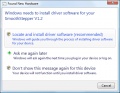
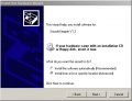
Select “Locate and install driver software (recommended)”

Select “I don’t have the disc” and click Next.
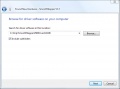
Click the “Browse” button and select the folder containing the SmoothStepper drivers.
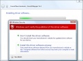
Select “Install this driver software anyway”. This warning is because the driver is not digitally signed.
The drivers will install.

Upon successful installation you will see this dialog box.


Installing Plug-In
With the driver installed, the computer is ready to talk to the SmoothStepper device. The PlugIn for Mach3 is the application that will be doing that. This section describes how to install the PlugIn.
The Mach3 PlugIn for the SmoothStepper is available as an “m3p” file on the Warp9TD website’s Downloads page:
http://warp9td.com/downloads.htm
Save the file to a convenient place on your computer.
An “m3p” file is a “Mach3Plugins” file. It is the same thing as the dll file that is located in the Mach3 PlugIns folder. It is provided in this form because it becomes a simple matter of installing the file by double-clicking it. When you double click it, the file will automatically be copied to the Mach3 PlugIns folder, and its extension will be changed to dll.
Configuring Mach3
With drivers and PlugIn installed and the SmoothStepper connected to the USB port, it is time to prepare Mach3 for the SmoothStepper. A steady blue LED (power on) and a steady red LED (firmware not loaded) should be illuminated on the SmoothStepper board.
One computer running Mach3 can have several different profiles to run different machines or the same machine in different configurations. The configuration files for these profiles have the extension .xml.
If you already have a working system it is important to preserve your existing profile. Mach3 has the ability to create a new profile that is a clone of your existing profile. This allows all your settings to be transferred to the clone, which can then be modified to work with the SmoothStepper, leaving youroriginal profile intact. It is not good to use one XML file and change it back and forth between SmoothStepper and printer port. Make a copy of your XML file and store it in a safe place, leaving the original in your Mach3 folder.
If you are setting up Mach3 for the first time, just select either Mach3Mill or Mach3Turn from the Session Profile dialog box.
To make a clone of your settings go to your Mach3 folder and double click on Mach3.exe. The following dialog box will appear:

Click “Create Profile"
Mach3 will now load with your new profile. Since the SmoothStepper PlugIn has been installed in the Mach3/PlugIns file, Mach3 will display a dialog box asking you to choose a control device. Listed are all the control device PlugIns that are in the Mach3/PlugIns folder. Note that the name of the SmoothStepper PlugIn is the filename of PlugIn that you installed in the previous section. If you don’t see a choice for the SmoothStepper, return to the Plugin Installation Section of this manual.

In the “Clone From” window, select your current working profile. In the “New Profile Name” window, type in the name you want to use for your SmoothStepper profile. Click “OK”.
You now have a new profile, with all your settings, ready to configure for SmoothStepper operation.

Highlight your new profile in the “Current Profile” window and click “OK”
The SmoothStepper PlugIn will now do most of the configuration automatically. When it is done you should see the blue power-on LED, a steady green LED indicating that the PlugIn has loaded the firmware automatically and a blinking red LED that indicates Mach3 is transmitting data to the device.
Close Mach3. The red led should be solid, and the green led should go out. This means the firmware has been unloaded.
Launch Mach3 using the profile you made for the SmoothStepper. If started with a cloned profile of a working system, all the port and pin assignments should work with no modification. If you are setting up Mach3 for the first time, see Mach3 documentation for instructions. If your motor tunings are such that the maximum step frequency is greater than 256 kHz, you will need to change the settings in the SmoothStepper PlugIn Config. See the next section for details. If you do not do this, the SmoothStepper’s counters will overflow and you will lose or gain steps. Be sure to check your motor tunings to make sure they are set properly. The max step frequency settings of the SmoothStepper may affect them.
The strip of 11 green screw terminals is meant for encoders, but may be used as input pins, just the same as the pins on the two parallel ports. This port is number “3” when you make assignments in the Ports & Pins Config. Per the silk screen on the board, the Port 3 assignments are as follows:
| Signal | Port 3 Pin Number |
|---|---|
| 1A | 1 |
| 1B | 2 |
| 1I | 3 |
| 2A | 4 |
| 2B | 5 |
| 2I | 6 |
Closing Mach3 and reopening it will force Mach3 to save the values to the XML file. For most parallel port settings (such as these) you can save the config settings by selecting the pulldown menu option under “Config”, but this will not save all the SmoothStepper settings. The safest sure way is to restart Mach3.
Optimizing SmoothStepper Operation
There are two configuration screens for the SmoothStepper, both are found under the “PlugIn Control” pull-down menu.

The first, is a configuration screen for SmoothStepper communication with Mach3. It sets the amount of data that is sent from Mach3 to the SmoothStepper, and the maximum pulse frequency for each axis. Included also is the opportunity to configure the I/O configuration of the second port.

If in doubt, set the values to 4 MHz. The only drawback is that the motion might not be as smooth. But the SmoothStepper’s counters will not overflow.
Select “PWM” if you wish to use that mode of operation. Otherwise it will default to Step & Direction. The base frequency is the frequency of the PWM signal. PWM stands for “Pulse Width Modulation”. The frequency is constant, but the pulse width (duty cycle) changes.
If you make any changes to this screen, please retune your motors (see the Mach manual for details) and restart Mach3.
The “Data Monitoring” screen shows the data flow between Mach3 and the SmoothStepper board.

Connecting the SmoothStepper to Your Machine
The SmoothStepper is intended to be used with breakout boards that make it easier to wire motors and switches, as well as protect it from damaging voltages by way of optical isolation. Optical isolation also keeps electrical noise from one circuit away from another since the signals are transferred by light rather than electricity. If you are using an external 5V supply, please see section 7.1 before connecting the SmoothStepper to anything.
This section of the manual still needs a fair amount of material to be complete. Please check back later for updates.
Using an External 5V Supply
The SmoothStepper may be powered from either the 5V of the USB cable, or a regulated 5V supply. It absolutely must not peak any higher than 5.5V, otherwise you will damage the device. External 5V may be applied via the pluggable screw terminal J7, or it may also be applied via jumpers JP2 and JP3. These jumpers are meant for breakout boards, and it is not recommended to use them unless you’re using them that way. If you are using this method of powering the SmoothStepper, you should be very sure to move the power selection jumper JP4 to the External 5V position. Otherwise, you would be connecting the external 5V on pin 26 of the header to the computer’s USB supply.
There is no reverse polarity protection for JP2 and JP3. However, J7 has a PMOS transistor in series with the positive lead to protect against the accidental connection of power in the wrong polarity. But before you connect the 5V to the device, disconnect all cables, including the USB cable. Otherwise, if you have the polarity backwards, you will be connecting +5V to the ground of your system. This can damage your computer and the ground of the SmoothStepper. If there is no return path to ground, there is nothing to worry about. The PMOS transistor blocks the current in the reverse direction, and current from the +5V supply goes nowhere because the ground of the SmoothStepper is insulated from everything.
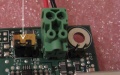
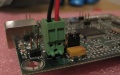
Select external 5V by moving jumper JP4 (unfortunately the “JP4” designator is hidden by the large yellow capacitor) to the two terminals away from the USB connector. The middle pin of the three pins is the 5V for the board, and this is either jumpered to the USB 5V or the external 5V (screw terminals).
The screw terminals are “pluggable”, that is, they may be unplugged from the board. The 11-pin terminal is actually composed of several 2 and 3-pin connectors, so don’t be alarmed if it starts to come apart as you pull it off. Also note that these connectors can be plugged onto their headers in one of two orientations. One is with the wires facing up, and one with them facing out.
The polarity of the external 5V is printed on the PCB in front of 2-terminal screw terminal. Ground is the terminal closest to the mounting hole. This is the only mounting hole of the four that connects to the ground of the circuit board (all the other holes do not connect to anything). Jumper JP5 right next to the hole connects this hole to the ground of the PCB. You may connect it as you see fit. If you connect the 5V with the correct polarity, the blue power LED will be lit. If not, no LEDs will be lit. Once you have the 5V connected properly, then you may proceed. If you are using the 5V from the USB, there is no way to connect it improperly.

Jumper in USB 5V Position
Jumper in External 5V Position

Connector in Horizontal Position
Connector in Vertical Position


Connect to a Breakout Board
The SmoothStepper was designed to be a parallel port replacement. You should be able to connect its I/O ports directly to a breakout board and follow the instructions for that piece of hardware. This manual will be expanded to cover this topic in detail.
Specifications
6 axes of coordinated movement plus a spindle.
Spindle control may be Step & Direction, PWM, or discrete on/off.
Maximum Step Frequency is 4 MHz
I/O: Port 1: 12 Outputs and 5 Inputs
Port 2: 12 Outputs and 5 Inputs -or- 4 Outputs and 13 Inputs
Port 3: 6 Inputs (3 differential and 3 single-ended)
Grand Total: 24 Outputs and 16 inputs, or 16 outputs and 24 inputs, depending upon configuration.
All outputs are 5V CMOS logic.
Port 2 pins 2-9 have CMOS thresholds (input and output).
All other inputs are TTL, except for 3 of them that are differential and are intended to be used with an encoder. Except for Port 2 pins 2-9 and the differential inputs, all other inputs are Schmitt Triggers.
All outputs capable of sinking or sourcing 32 mA.
An expansion port is available for future expansion, which will allow for practically unlimited I/O that does not have a high speed requirement (roughly 10 Hz, which is as fast as Mach3 processes most I/O).
The interface to the computer is through an FTDI FT245RL USB chip. The interface is Full Speed USB, which is 12 Mbps. USB 1.1 or 2.0 required.
Power Requirements depend upon load. You may optionally choose to power from either the USB 5V or an external 5V (via screw terminals or pin 26 of either 26-pin header).
Troubleshooting
TBD