PDB I/O Board
The I/O Board is the main place where connections are made to the ancillary boards in the extrusion head, X, Y motors, limit switches and front panel display. It is also where the main chamber's thermocouple is connected along with an on board analog-to-digital converter.

| Diagram |
PCB Designation |
Connection |
Function
|
| A |
J510 (PDB 1) |
|
Board to Board Interconnect to the Power Distribution Card (PDC)
|
| B |
J511 (PDB 2) |
|
Board to Board Interconnect to the Power Distribution Card (PDC)
|
| C |
J507 (CHAMBER TC) |
Omega PCC-SMP-K |
Chamber Thermocouple
|
| D |
J501 (Y-MOTOR) |
Molex Microfit 3.0 (4-Pin) |
Y-Axis Motor
|
| E |
J502 (X-MOTOR) |
Molex Microfit 3.0 (6-Pin) |
X-Axis Motor
|
| F |
J503 (Y SENSORS) |
Molex Microfit 3.0 (18-Pin) |
Y-Axis Limit Switches
|
| G |
J504 (UPPER HARNESS) |
Molex Microfit 3.0 (24-Pin) |
Front Panel & Chassis wiring (blower fan, on/off switch, chamber lights, door solenoid and magnetic door switch)
|
| H |
J505 (UMB1) |
Molex Microfit 3.0 (22-Pin) |
Umbilical head harness 1. (Model and support heaters, toggle switch sensor, X-axis limit switches)
|
| I |
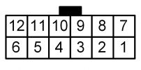
J506 (UMB2) |
Molex Microfit 3.0 (12-Pin) |
Umbilical head harness 2 (Print bed level sensor, head drive motor, model and support thermocouple)
|
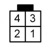
J501 (Y-MOTOR)
This connection connects the electronics to the Y-Axis motor (forward and back motion). This is a Molex Microfit 3.0 connector with 4 positions.

| Pin |
Wire Color |
Function
|
| 1 |
Black |
A+
|
| 2 |
Blue |
B+
|
| 3 |
Green |
A-
|
| 4 |
Red |
B-
|
J502 (X-MOTOR)
This connection connects the electronics to the X-Axis motor (side to side motion). This is a Molex Microfit 3.0 connector with 6 positions.

| Pin |
Wire Color |
Function
|
| 1 |
Black |
A+
|
| 2 |
- |
N/C
|
| 3 |
Black |
B+
|
| 4 |
Black |
A-
|
| 5 |
- |
N/C
|
| 6 |
Black |
B-
|
J503 (Y SENSORS)

| Pin |
Wire Color |
Function
|
| 1 |
- |
NC
|
| 2 |
- |
NC
|
| 3 |
Red |
+Vcc
|
| 4 |
Red |
+Vcc
|
| 5 |
Yellow |
Y-Axis End of Travel Limit Switch
|
| 6 |
- |
NC
|
| 7 |
- |
NC
|
| 8 |
- |
NC
|
| 9 |
- |
NC
|
| 10 |
- |
NC
|
| 11 |
Green |
Ground
|
| 12 |
Yellow |
Y-Axis Home Limit Switch
|
| 13 |
Green |
Ground
|
| 14 |
- |
NC
|
| 15 |
- |
NC
|
| 16 |
- |
NC
|
| 17 |
- |
NC
|
| 18 |
- |
NC
|
J504 (UPPER HARNESS)

| Pin |
Wire Color |
Function
|
| 1 |
Red |
Front LCD, unknown function
|
| 2 |
White |
Front LCD, unknown function
|
| 3 |
Blue |
Front LCD, unknown function
|
| 4 |
Orange |
Front LCD, unknown function
|
| 5 |
- |
NC
|
| 6 |
Yellow |
Power Switch
|
| 7 |
Yellow |
Magnetic Sensor
|
| 8 |
White |
Door Solenoid
|
| 9 |
Black |
LED Lighting (Negative)
|
| 10 |
Black |
LED Lighting (Negative)
|
| 11 |
- |
NC
|
| 12 |
Black |
Head Blower Fan (Positive)
|
| 13 |
Green |
Front LCD, unknown function
|
| 14 |
Yellow |
Front LCD, unknown function
|
| 15 |
Green |
Front LCD, unknown function
|
| 16 |
- |
NC
|
| 17 |
- |
NC
|
| 18 |
Green |
Power Switch
|
| 19 |
Green |
Magnetic Sensor
|
| 20 |
Black |
Door Solenoid
|
| 21 |
Red |
LED Lighting (Positive)
|
| 22 |
Red |
LED Lighting (Positive)
|
| 23 |
- |
NC
|
| 24 |
Red |
Head Blower Fan (Negative)
|
J505 (UMB1)

| Pin |
Wire Color |
Function
|
| 1 |
Black |
Model Heater (Negative)
|
| 2 |
Blue |
Model Heater (Positive)
|
| 3 |
Green |
Support Heater (Positive)
|
| 4 |
Black |
Support Heater (Negative)
|
| 5 |
Green |
Ground
|
| 6 |
Blue |
Ground
|
| 7 |
Purple |
TBD, Thermocouple Wiring
|
| 8 |
- |
NC
|
| 9 |
- |
NC
|
| 10 |
Black |
Toggle Limit Switch
|
| 11 |
Grey |
X-Axis End of Travel Limit Switch
|
| 12 |
- |
NC
|
| 13 |
- |
NC
|
| 14 |
- |
NC
|
| 15 |
- |
NC
|
| 16 |
- |
NC
|
| 17 |
White |
TBD, Thermocouple Wiring
|
| 18 |
- |
NC
|
| 19 |
- |
NC
|
| 20 |
- |
NC
|
| 21 |
White |
Toggle Limit Switch
|
| 22 |
Red |
X-Axis Home Limit Switch
|
J506 (UMB2)

| Pin |
Wire Color |
Function
|
| 1 |
Brown |
Ground
|
| 2 |
Red |
+5VDC
|
| 3 |
Orange |
Extruder Servo Motor Encoder Pin 8
|
| 4 |
Yellow |
Extruder Servo Motor Power (Positive)
|
| 5 |
Black |
TBD, Thermocouple Wiring
|
| 6 |
Red |
TBD, Thermocouple Wiring
|
| 7 |
Purple |
Print Bed Limit Switch
|
| 8 |
Grey |
Extruder Servo Motor Encoder Pin 6
|
| 9 |
White |
Extruder Servo Motor Power (Negative)
|
| 10 |
Black |
TBD, Thermocouple Wiring
|
| 11 |
Yellow |
TBD, Thermocouple Wiring
|
| 12 |
Black |
TBD, Thermocouple Wiring
|


