Difference between revisions of "Parallel Breakout Board"
From CNC.xyz Wiki
| (10 intermediate revisions by the same user not shown) | |||
| Line 1: | Line 1: | ||
{{Infobox | {{Infobox | ||
|title = Parallel Breakout Board | |title = Parallel Breakout Board | ||
| − | |image = | + | |image = [[File:Parallel Breakout Board.jpg|200px]] |
| − | |caption = | + | |caption = Parallel Breakout Board |
|label2 = Status | |label2 = Status | ||
|data2 = In Development | |data2 = In Development | ||
| Line 15: | Line 15: | ||
}} | }} | ||
| − | + | The Parallel Breakout Board is one of the simplest and yet one of the most important parts for a traditional CNC machine. This parallel breakout board will take a signal from a male DB-25 connector and will convert the signal to an easy to access terminal block for direct wiring. Pins 1-17 are broken out according to a standard [[Parallel Port]] specification. Pins 18-25 are connected to ground. | |
| + | |||
| + | {{Clear}} | ||
| + | |||
| + | ==Features== | ||
| + | *Easy adapter that breaks out the parallel port and converts to board to wire connectors. | ||
| + | *Access to pins 1-17 of the parallel port. Pins 18-25 are grounded. | ||
| + | |||
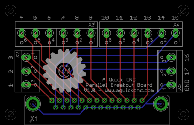
| + | ==Board Layout== | ||
| + | The board is 2.80" x 1.80" with mounting holes at 2.50" x 1.50" with 4mm holes (#6 screws can be used if 4mm screws are not available). | ||
[[File:Parallel Breakout Board Layout.png|400px]] | [[File:Parallel Breakout Board Layout.png|400px]] | ||
| − | [[:File:Parallel Breakout Board Schematic.pdf|Schematic PDF Download]] | + | ==Schematic== |
| + | |||
| + | [[File:Parallel Breakout Board Schematic.png|300px]] | ||
| + | |||
| + | *[[:File:Parallel Breakout Board Schematic.pdf|Schematic PDF Download]] | ||
==Bill of Materials (BOM)== | ==Bill of Materials (BOM)== | ||
| − | |||
| − | |||
| − | |||
| − | |||
| − | |||
| − | |||
| − | |||
| − | |||
| − | |||
| − | |||
| − | |||
| − | |||
| − | |||
| − | |||
| − | |||
| − | |||
| − | |||
| − | |||
| − | |||
| − | |||
| − | |||
| − | |||
| − | |||
| − | |||
| − | |||
| − | |||
| − | |||
| − | |||
| − | |||
| − | |||
| − | |||
| − | |||
| − | |||
| − | |||
| − | |||
| − | |||
{| class="wikitable" | {| class="wikitable" | ||
| Line 63: | Line 40: | ||
! Line # !! Quantity !! Part Code !! Digikey !! Description | ! Line # !! Quantity !! Part Code !! Digikey !! Description | ||
|- | |- | ||
| − | | 1 || 1 || X1 || [http://www.digikey.com/short/ | + | | 1 || 1 || X1 || [http://www.digikey.com/short/jdm7c AE10982-ND] || DB-25 Male Right Angle Connector |
|- | |- | ||
| − | | 2 || | + | | 2 || 2 || X2, X5 || [http://www.digikey.com/short/jdmc7 ED2610-ND] || 3 Position Terminal Block |
|- | |- | ||
| 6 || 2 || X3, X4 || [http://www.digikey.com/short/j2vhn ED2613-ND] || 6 Position Terminal Block | | 6 || 2 || X3, X4 || [http://www.digikey.com/short/j2vhn ED2613-ND] || 6 Position Terminal Block | ||
|} | |} | ||
| + | ==Gerber Files== | ||
| + | [[:File:Parallel Breakout Board Gerber.zip|Gerber File Download]] | ||
| + | ==Eagle Files== | ||
[[:File:Parallel Breakout Board Eagle.zip|Eagle File Download]] | [[:File:Parallel Breakout Board Eagle.zip|Eagle File Download]] | ||
| − | |||
| − | |||
==License== | ==License== | ||
This work is licensed under a [http://creativecommons.org/licenses/by-sa/3.0/ Creative Commons Attribution-ShareAlike 3.0 Unported License]. | This work is licensed under a [http://creativecommons.org/licenses/by-sa/3.0/ Creative Commons Attribution-ShareAlike 3.0 Unported License]. | ||
Latest revision as of 23:00, March 1, 2014
 Parallel Breakout Board | |
| Status | In Development |
|---|---|
| Manufacterer | A Quick CNC |
| Version | 1.0.0 |
| Designer | AJ Quick |
| License | CC BY-SA 3.0 |
The Parallel Breakout Board is one of the simplest and yet one of the most important parts for a traditional CNC machine. This parallel breakout board will take a signal from a male DB-25 connector and will convert the signal to an easy to access terminal block for direct wiring. Pins 1-17 are broken out according to a standard Parallel Port specification. Pins 18-25 are connected to ground.
Contents
Features
- Easy adapter that breaks out the parallel port and converts to board to wire connectors.
- Access to pins 1-17 of the parallel port. Pins 18-25 are grounded.
Board Layout
The board is 2.80" x 1.80" with mounting holes at 2.50" x 1.50" with 4mm holes (#6 screws can be used if 4mm screws are not available).
Schematic
Bill of Materials (BOM)
| Line # | Quantity | Part Code | Digikey | Description |
|---|---|---|---|---|
| 1 | 1 | X1 | AE10982-ND | DB-25 Male Right Angle Connector |
| 2 | 2 | X2, X5 | ED2610-ND | 3 Position Terminal Block |
| 6 | 2 | X3, X4 | ED2613-ND | 6 Position Terminal Block |
Gerber Files
Eagle Files
License
This work is licensed under a Creative Commons Attribution-ShareAlike 3.0 Unported License.

